
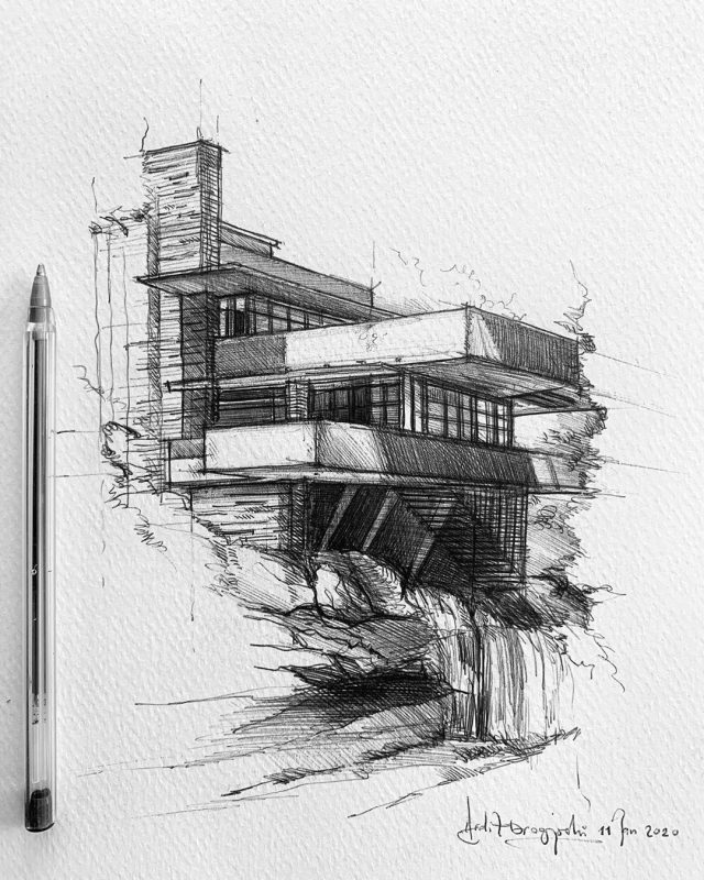
Architectural Drawings: A Guide to Reading and Creating Building Plans
Architectural drawings turn ideas about a building into clear instructions for designing, reviewing, and constructing it. They communicate a project’s size, shape, layout, materials, and technical details to clients, architects, engineers, contractors, and permitting officials. Whether drawn by hand or created with digital design software, these documents help everyone involved understand how a building is intended to work.
What Are Architectural Drawings?
Architectural drawings are scaled representations of a building or space. They may show the overall design, individual rooms, exterior elevations, construction details, or the relationship between a building and its site. A complete drawing set typically contains multiple views because no single drawing can explain every aspect of a project.
Drawings can be created during different stages of a project. Early sketches explore possibilities, while later documents provide increasingly precise information for approvals and construction. The required drawings vary depending on the project’s size, location, and complexity.
Common Types of Architectural Drawings
Floor Plans
A floor plan is a top-down view of a building, as if it were cut horizontally above the floor. It shows room layouts, walls, doors, windows, stairs, and other features. Dimensions and labels help readers understand the size and intended use of each space.
Elevations
Elevations show the exterior or interior face of a building from a straight-on viewpoint. They communicate the heights, proportions, openings, finishes, and architectural features of a wall or façade. Common views include the front, rear, and sides of a building.
Sections
A section shows a building as if it were sliced vertically. This view can reveal floor-to-floor heights, roof construction, stairways, structural relationships, and how different spaces connect. Sections are especially useful for understanding features that are difficult to interpret from a floor plan alone.
Site Plans
A site plan shows how a building relates to its property and surroundings. It may include property boundaries, access roads, parking areas, walkways, landscaping, utility connections, and nearby structures. Site plans are often important for planning and permit reviews.
Detail Drawings
Detail drawings focus on a small part of a project at a larger scale. They might explain how a window meets a wall, how a railing is attached, or how materials connect at a roof edge. These details help resolve construction questions that cannot be explained clearly in a general plan or elevation.
How to Read an Architectural Drawing
Begin by checking the title block, usually located along the edge or bottom of the sheet. It commonly identifies the project, drawing title, scale, issue date, and drawing number. The revision information can indicate whether a sheet has been updated.
Next, look for the scale and orientation. A drawing scale relates the dimensions on the page to actual measurements. A north arrow may appear on a site plan, while elevation labels or section markers identify the direction of a view. Always rely on written dimensions rather than estimating measurements from a printed drawing, since printing or screen resizing can change the apparent scale.
Architectural drawings also use symbols, line types, abbreviations, and notes. A legend or drawing key explains project-specific symbols. Heavier lines often represent elements cut through in a plan or section, while lighter lines may show objects beyond the cut, such as cabinets or overhead features. Conventions can vary, so notes and legends should be reviewed rather than assumed.
Scale, Dimensions, and Annotations
Scale allows a large building to be represented on a manageable sheet. Different views may use different scales: a site plan generally shows a broad area, while a construction detail provides a close-up. The scale should be clearly identified for each drawing or group of drawings.
Dimensions provide direct measurements for important locations and components. Notes may identify materials, finishes, installation requirements, or design intent. When information appears inconsistent between drawings, it should be clarified with the design team before work proceeds.
From Concept to Construction
The drawing process typically begins with a discussion of the client’s needs, budget, site, and goals. The design team develops concepts, studies the layout, and revises the proposal based on feedback. As the design becomes more defined, the drawings gain detail.
Depending on the project, the team may coordinate architectural drawings with structural, mechanical, electrical, plumbing, and civil documents. This coordination helps identify conflicts, such as a duct passing through a beam or a pipe competing for space with another building system.
Construction drawings communicate design decisions, but they are not a substitute for professional judgment or required inspections. Local codes, permitting rules, and licensing requirements vary. Project owners should work with qualified professionals familiar with the regulations that apply to their location and building type.
Hand Drafting and Digital Tools
Architects have long used hand drafting to develop and communicate designs. Drawing by hand can be valuable for sketching ideas quickly and exploring proportions. Today, many projects are developed with computer-aided design (CAD) software or building information modeling (BIM) tools.
Digital tools make it easier to revise drawings, coordinate information, and produce consistent documents. BIM can connect a three-dimensional building model with information about components and systems. However, software does not replace careful design, accurate input, or clear communication. A drawing is useful only when its information is understandable and reliable.
Why Architectural Drawings Matter
Clear architectural drawings help align expectations before construction begins. They support decision-making, assist with cost estimates, provide information for permit applications, and guide contractors as they build. Thorough documentation can also reduce confusion and help teams identify issues earlier in the process.
Ultimately, architectural drawings are more than pictures of a proposed building. They are a shared language for turning design goals into a coordinated, buildable project. Understanding their views, symbols, dimensions, and notes makes it easier to participate in that process and see how a design takes shape.
9 Essential Tips for Creating Clear and Accurate Architectural Drawings
- Use consistent line weights to show depth and importance.
- Add dimensions that are clear and complete.
- Label rooms, materials, and key features.
- Keep symbols and abbreviations consistent.
- Include a north arrow on site plans.
- Use a readable scale and state it clearly.
- Coordinate plans, elevations, and sections.
- Check door swings and circulation paths.
- Review drawings for accuracy before sharing.
Use consistent line weights to show depth and importance.
Use consistent line weights to make architectural drawings easier to read and understand. Heavier lines can highlight elements that are cut through or especially important, while lighter lines can show surfaces, details, or objects farther in the background. Applying these weights consistently helps communicate depth and hierarchy at a glance, so viewers can quickly distinguish major structural features from secondary information.
Add dimensions that are clear and complete.
Add dimensions that are clear and complete so everyone can understand the size and location of each important feature. Include the measurements needed to lay out walls, openings, rooms, and key building elements, and make sure dimension lines and labels are easy to read and don’t overlap. Use consistent units and conventions, and check that the dimensions agree across related drawings. Clear, coordinated measurements reduce guesswork and help prevent costly errors during construction.
Label rooms, materials, and key features.
Labeling rooms, materials, and key features makes architectural drawings easier to read and helps everyone involved understand the design. Clear room names show how each space is intended to be used, while material labels identify finishes and construction elements such as flooring, siding, or countertops. Callouts for important features—like doors, windows, built-in storage, and accessibility details—can prevent confusion during reviews and construction. Keep labels consistent, legible, and coordinated with the drawing legend and notes.
Keep symbols and abbreviations consistent.
Keep symbols and abbreviations consistent throughout architectural drawings to make the plans easier to read and reduce the risk of misinterpretation. Use the same symbol for the same feature on every sheet, and define uncommon abbreviations in a clear legend or notes section. Consistent conventions help architects, engineers, contractors, and reviewers quickly find the information they need and coordinate their work with confidence.
Include a north arrow on site plans.
Include a north arrow on every site plan to show the property’s orientation. This simple symbol helps readers understand how the building and site relate to the cardinal directions, nearby streets, sunlight, and surrounding features. Place it where it is easy to see, and make sure it points to true north or clearly indicate if it represents a different orientation.
Use a readable scale and state it clearly.
Use a readable scale and state it clearly on every architectural drawing. The scale should show how measurements on the page relate to real-world dimensions, making the drawing easier to interpret and use. Choose a scale that provides enough detail for the information shown, and label it prominently so readers don’t have to guess. If a drawing is resized or viewed digitally, include written dimensions as well, since the displayed scale may no longer be accurate.
Coordinate plans, elevations, and sections.
Coordinate plans, elevations, and sections so they tell a consistent story of the design. A floor plan shows the layout from above, elevations show faces of the building, and sections reveal what happens vertically through it. Check that key features—such as doors, windows, stairs, floor levels, and structural elements—align across all views. Consistent dimensions, labels, and references help prevent confusion during review and construction.
Check door swings and circulation paths.
Check door swings and circulation paths to make sure doors can open fully without hitting walls, furniture, fixtures, or other doors. Confirm that hallways and routes between rooms provide enough clear space for comfortable movement and accessibility. Reviewing these details on the drawings can reveal conflicts early, before they become costly or inconvenient to fix during construction.
Review drawings for accuracy before sharing.
Before sharing architectural drawings, review them carefully for accuracy and consistency. Check dimensions, labels, scales, notes, and symbols, and confirm that related plans, elevations, and sections agree. Make sure the drawing set shows the correct project information and revision dates, and that no key details are missing or unclear. A thorough review can help prevent misunderstandings, costly mistakes, and delays during approvals or construction.